How to use an airhdl register bank in a Xilinx Platform Studio (XPS) project
This article describes how to integrate an airhdl-generated register component into a Xilinx Platform Studio (XPS) project.
In this example, we will be creating a new peripheral called signal_processor and add a signal_processor_regs register component to it. The register component, which was created in airhdl, features only two registers:
- a read-write
controlregister with a 1-bitenafield - a read-only
statusregister with a 32-bitvaluefield
Step 1: Create the XPS Project
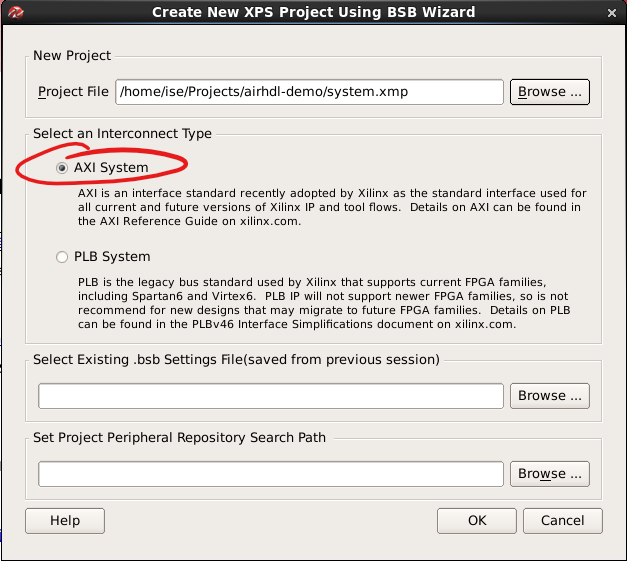
If you have not already done so, please open XPS and created a new project using the BSB Wizard. Select the AXI System type of interconnect as well as the MicroBlaze Processor System.
Step 2: Create a new peripheral
In this step we're going to create a new bus peripheral and add it to our system.
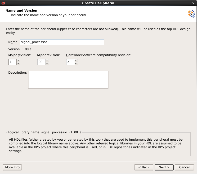
In the Hardware Menu, select Create or Import Peripheral... to bring up the Create or Import Peripheral Wizard. Leave all the defaults are they are and enter a name for your peripheral. In this example, we'll call it signal_processor:
Once you have set the name, click Next to show the Bus Interface view. Select AXI4-Lite:
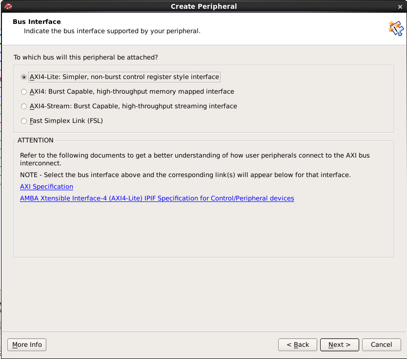
Leave the other options at their default values and click Finish to create the peripheral.
Step 3: Integrate the airhdl register component into the XPS peripheral
Step 3.1: Download the RTL files for your register map
Assuming that you're using VHDL as a hardware description language, log in to your airhdl account and download the VHDL Package and VHDL Component files corresponding to your register map.
Using a file system explorer, open your XPS project's directory, locate the pcores subdirectory and browse to the hdl/vhdl subdirectory corresponding to your newly created peripheral. In our examples, those files are located under pcores/signal_processor_v1_00_a/hdl/vhdl. Copy the two files you downloaded from your airhdl account into this directory:
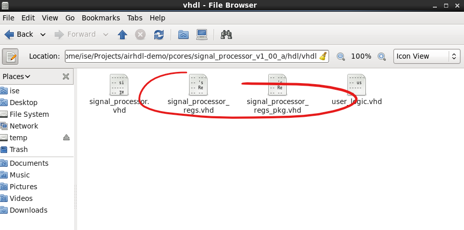
You may delete the user_logic.vhd file as we will not be using it.
Step 3.2: Cleanup the component's VHDL file
In a text editor of your choice, open the <your_component>.vhd file (e.g. signal_processor.vhd) and delete everything that follows the architecture declaration, leaving only an empty architecture declaration:
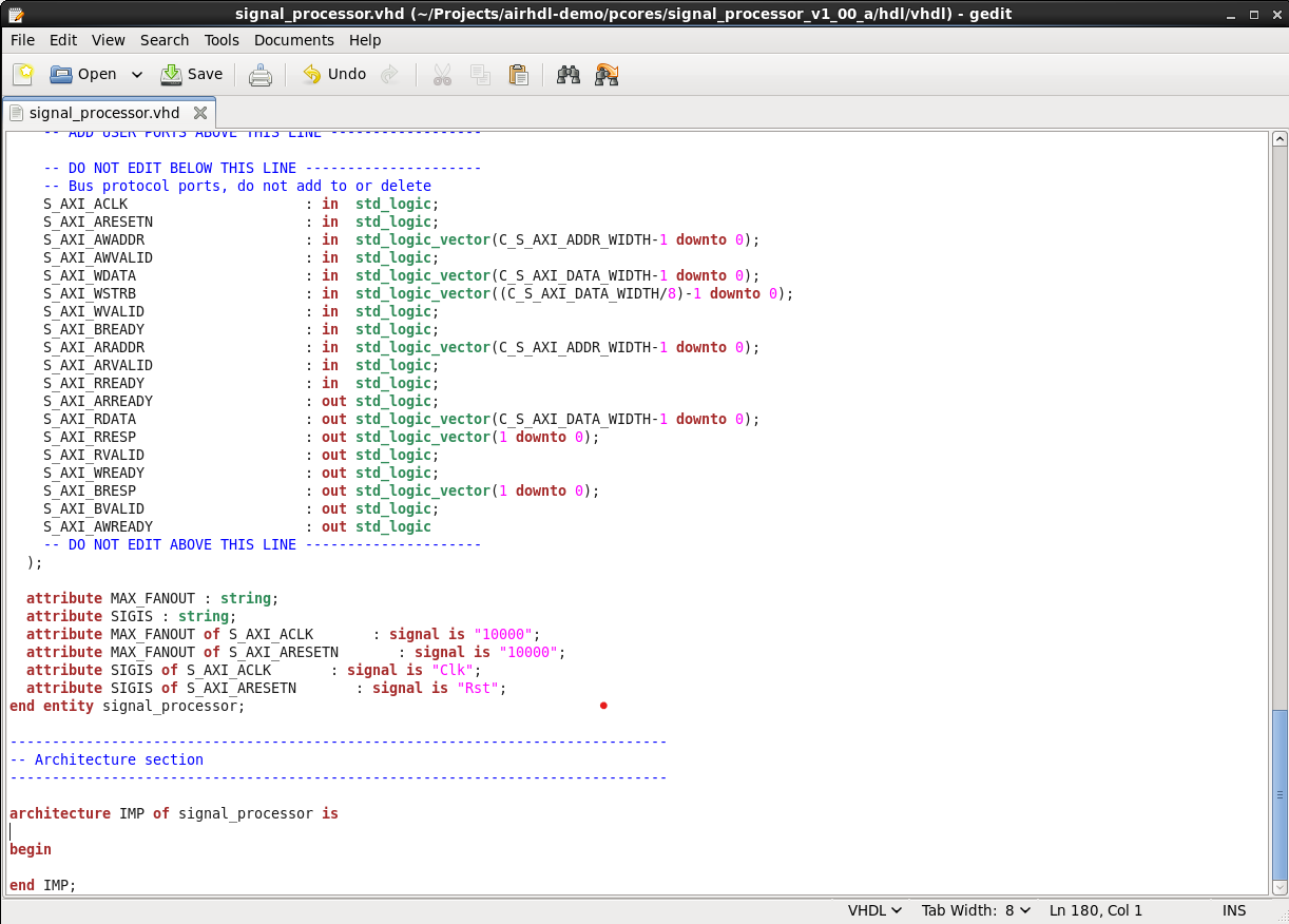
Step 3.3: Instantiate the register component
In the <your_component>.vhd that you just cleaned up in the step before, instantiate the <your_component>_regs airhdl register component, taking care to declare the signals that connect to the register component's user ports:
------------------------------------------------------------------------------
-- Architecture section
------------------------------------------------------------------------------

 architecture IMP of signal_processor is

     signal control_enable : std_logic_vector(0 downto 0);
     signal status_value : std_logic_vector(31 downto 0);

    begin

    signal_processor_regs : entity work.signal_processor_regs
    generic map (
        AXI_ADDR_WIDTH => C_S_AXI_ADDR_WIDTH,
        BASEADDR => C_BASEADDR
    )
    port map(
        -- Clock and Reset
        axi_aclk    => s_axi_aclk,
        axi_aresetn => s_axi_aresetn,
        -- AXI Write Address Channel
        s_axi_awaddr  => s_axi_awaddr,
        s_axi_awprot  => (others => '0'), -- don't care
        s_axi_awvalid => s_axi_awvalid,
        s_axi_awready => s_axi_awready,
        -- AXI Write Data Channel
        s_axi_wdata   => s_axi_wdata,
        s_axi_wstrb   => s_axi_wstrb,
        s_axi_wvalid  => s_axi_wvalid,
        s_axi_wready  => s_axi_wready,
        -- AXI Read Address Channel
        s_axi_araddr  => s_axi_araddr,
        s_axi_arprot  => s_axi_arprot,
        s_axi_arvalid => s_axi_arvalid,
        s_axi_arready => s_axi_arready,
        -- AXI Read Data Channel
        s_axi_rdata   => s_axi_rdata,
        s_axi_rresp   => s_axi_rresp,
        s_axi_rvalid  => s_axi_rvalid,
        s_axi_rready  => s_axi_rready,
        -- AXI Write Response Channel
        s_axi_bresp   => s_axi_bresp,
        s_axi_bvalid  => s_axi_bvalid,
        s_axi_bready  => s_axi_bready,
        -- User Ports
        control_strobe => open, -- don't care
        control_enable => control_enable,
        status_strobe => open, -- don't care
        status_value => status_value
    );

    -- User logic example:
    --  * increment a counter on every clock cycle when the control.enable bit is set.
    --  * drive the status.value register field with the value of the counter
    user_logic : process(s_axi_aclk) is
        variable count : unsigned(31 downto 0);
    begin
        if rising_edge(s_axi_aclk) then
            if s_axi_aresetn = '0' then
                count := (others => '0');
            else
                if control_enable = '1' then
                    count := count + 1;
                    status_value <= std_logic_vector(count);
                end if;
            end if;
        end if;
    end process;

end IMP;
As shown in the example above, <your_component>.vhd is also the place where you would instantiate the user logic for your component.
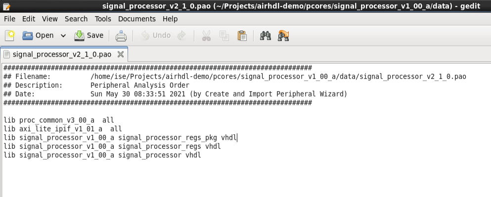
Step 3.4: Update the component's PAO file
Using a file system explorer, locate the Peripheral Analyze Order (PAO) file corresponding to your peripheral.
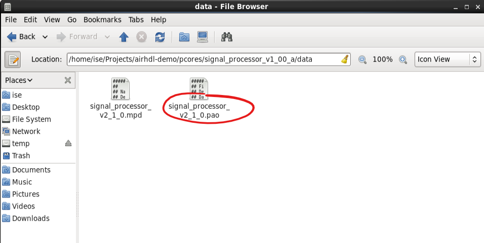
Open the PAO file in a text editor and update it to include your register component's entity (<your_component>_regs.vhd) and package files (<your_component>_regs_pkg.vhd). Make sure that the package file is listed before the entity file as the order of files matter. Delete the user_logic from the PAO file as we're not using it anymore.
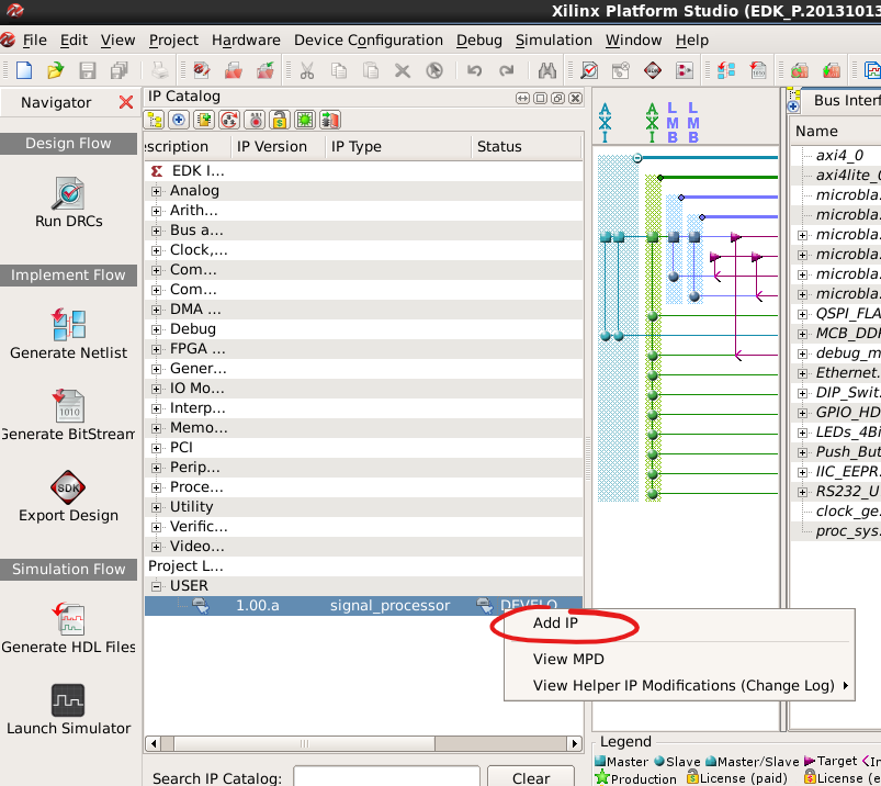
Step 4: Connect the peripheral to the system
In the project's IP catalog, locate the peripheral that you have created in the Project Local Pcores section, right-click on it an select Add IP:
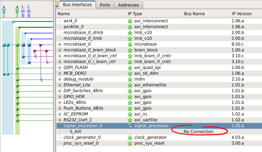
Check that your peripheral appears in the Bus Interfaces tab, expand the peripheral and click on the No Connection Button to bring up the Connection Dialog:
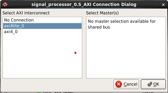
In the Connection Dialog, select the axi4lite interconnect and press OK:
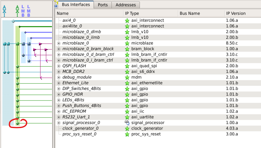
Check that the peripheral is connected to the AXI4-Lite bus, as signaled by the solid green dot in the diagram:
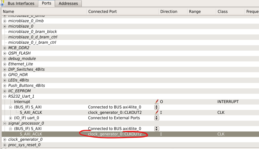
In the Ports tab, connect the S_AXI_ACLK port of your peripheral to the AXI4-Lite clock. You can check other, already connected components such as a UART to find out which clock source to connect to:
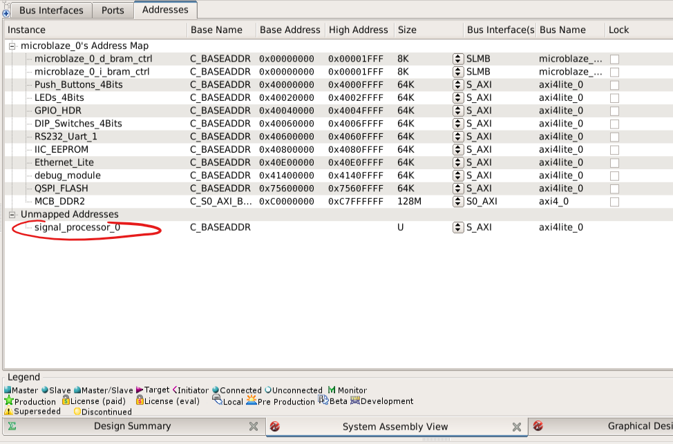
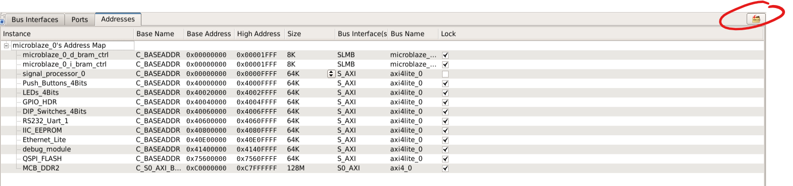
In the Adresses tab, locate your peripheral in the Unmapped Addresses section:
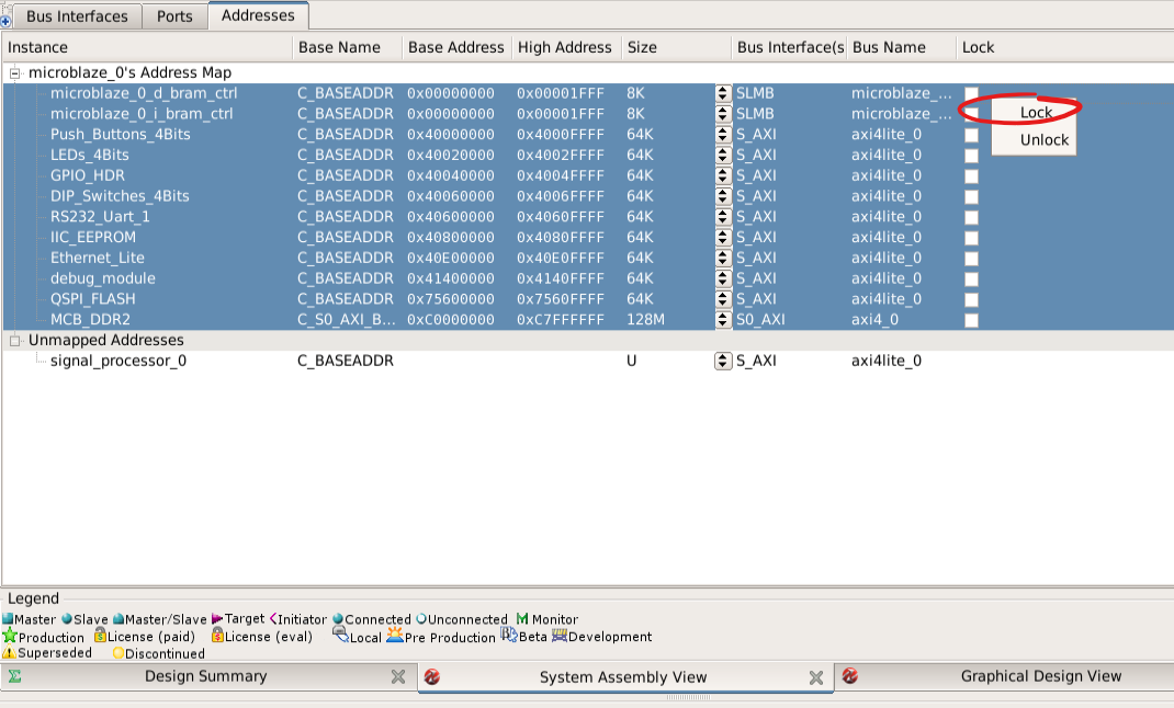
Select all the other, mapped addresses and lock them to prevent any unintended modifications:
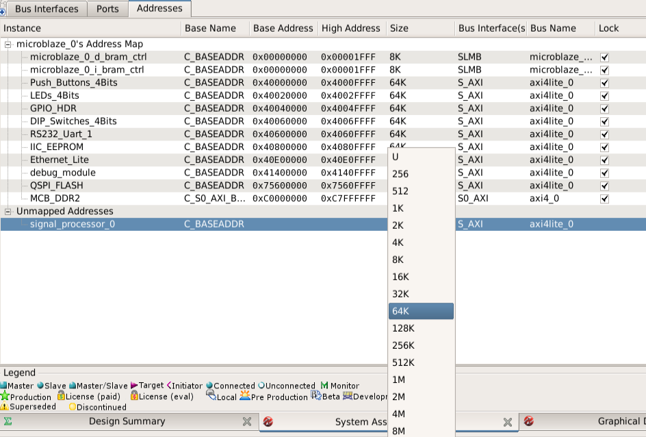
Set you peripheral's size property to a value large enough to accomodate your register map (e.g. 64K):
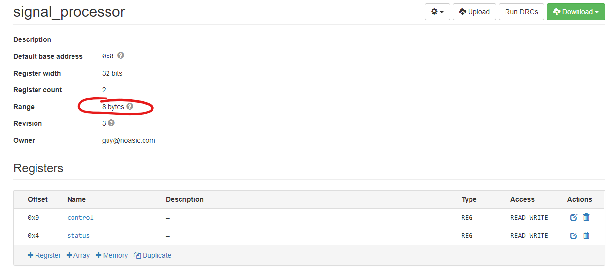
You can look up the size of your register map, i.e. the number of bytes it occupies in the address space, by looking at the register map's Range information in the airhdl web interface:
After that, the Adresses tab should not have any unmapped addresses anymore. Click on the Generate Addresses button to assign a valid base address to your peripheral:
Once you're done, click on the Run DRCs button to check that everything is connected correctly. If the DRCs pass successfully, you're free to proceed with the synthesis and implementation of the project.