Following several user requests, we added support for volatile register fields to the airhdl generator. Volatile fields are a special kind of read-write field whose write-value is set using an AXI4-Lite write transaction, and whose read-value originates from the user logic.
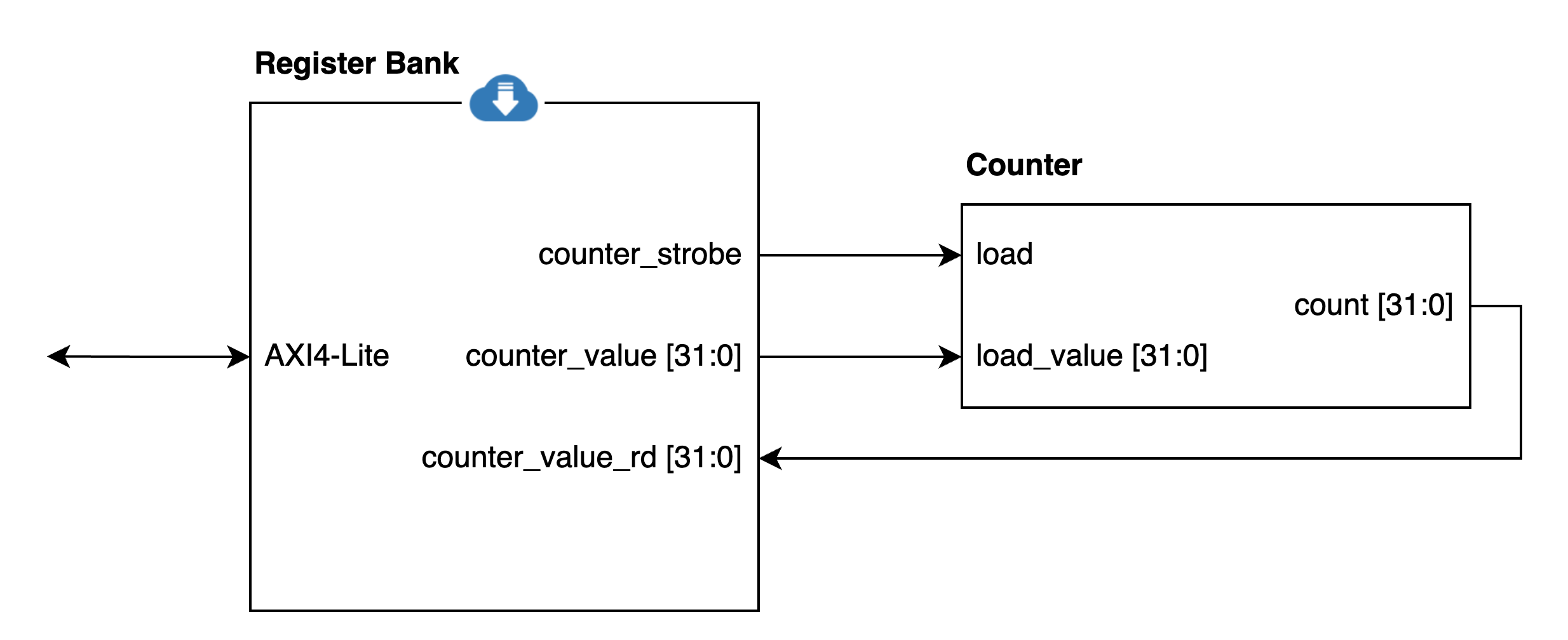
A typical application for volatile fields is time synchronization, where you want to read a counter value from the user logic, perform some adjustment on that value, and write it back to the hardware. Previously, this would have required two registers: a read-only register to read the current counter value, and a write-only register to update the counter value. Using the new volatile field, you can do it with just one counter register as shown in the diagram below:
An airhdl register bank with a volatile counter.value field allows reading a hardware counter and loading that counter to a new value through a single AXI4-Lite register.
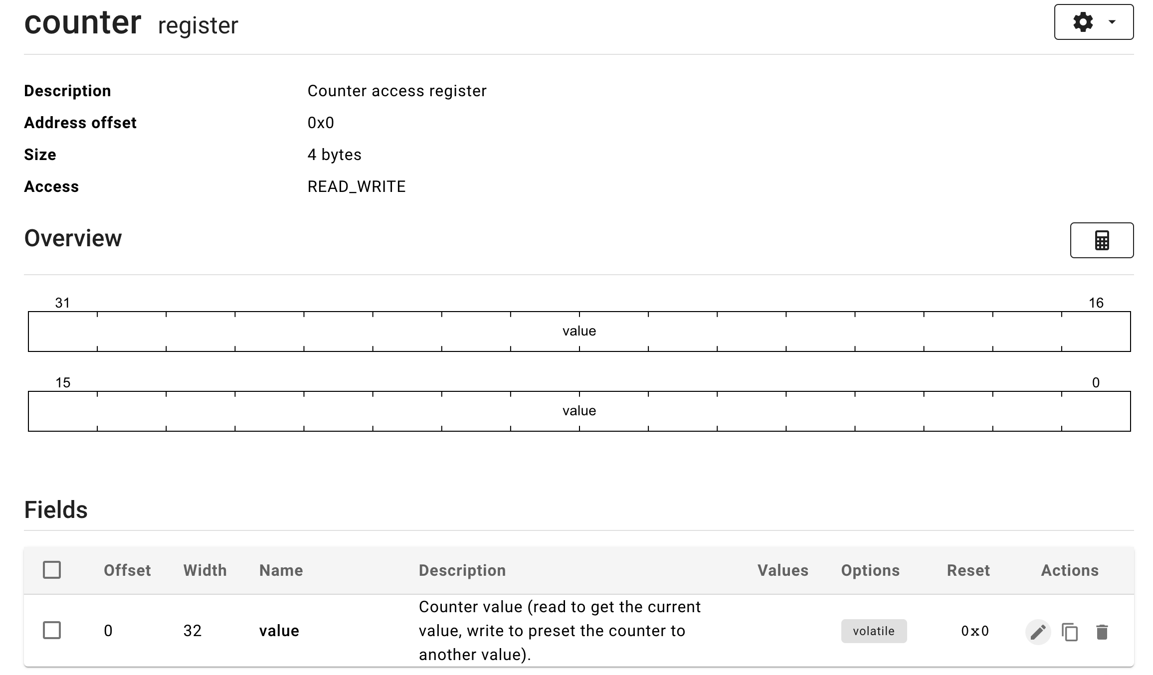
The diagram above assumes a read-write counter register with a volatile value field, which looks like this in the airhdl user interface:
Reading from the counter register over the AXI4-Lite interface returns the value of the register bank’s counter_value_rd input port, which reflects the current counter value.
Writing a new value to the counter register over the AXI4-Lite interface updates the corresponding counter_value port of the register bank and pulses the counter_strobe port, which has the effect of loading the new value into the external counter component.
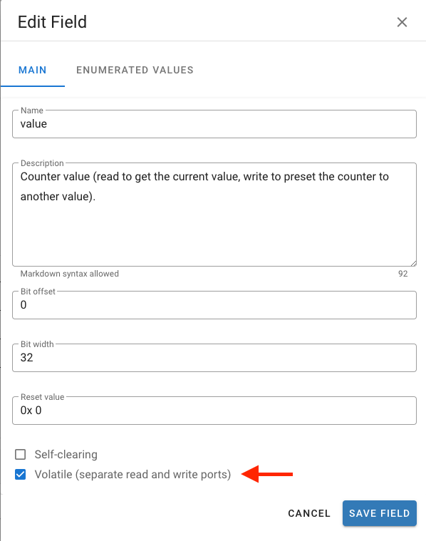
To create a volatile field within a read-write register or register array, activate the Volatile checkbox in the Create or Edit Field dialog:
Volatile fields are currently in beta and available to selected users. To get early access to this feature, please get in touch with support@airhdl.com.
Back in 2015, when I first attended Jim Lewis’ excellent Advanced VHDL Testbenches & Verification training in Bracknell (England), OSVVM was mostly a collection of VHDL packages that could be used to simplify the task of writing VHDL testbenches. At the time, OSVVM already included things like constrained random stimulus generation, scoreboards, functional coverage, and logging capabilities, but it wasn’t yet a one-stop shop for all your VHDL verification needs.
Fast forward a few years and thanks to Jim’s incredible work, OSVVM has become a world-class VHDL verification framework that is used by professional design teams around the world. Plus, when it comes to AXI4 verification, OSVVM probably has the most comprehensive set of verification components covering the AXI4, AXI4-Lite, and AXI4-Stream protocols.
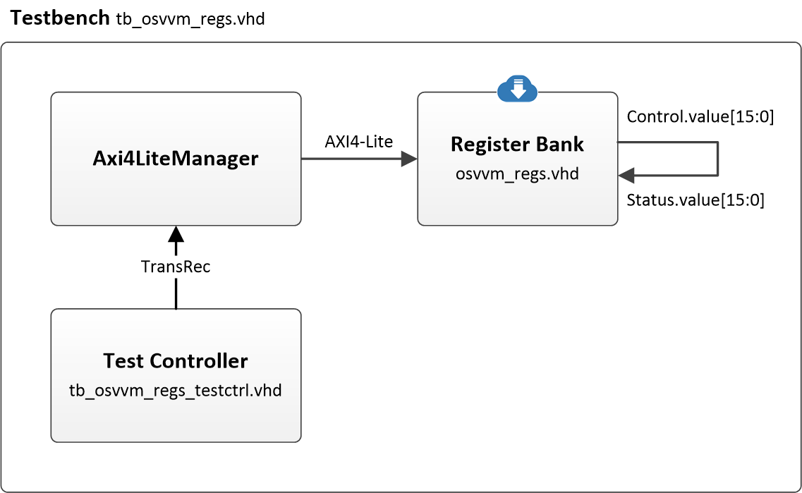
To show you how simple an OSVVM-style testbench for an AXI4-Lite slave component can be, I have created a small project called osvvm-demo, which you can find on the airhdl GitHub. The testbench, whose architecture is depicted in the diagram below, consists of the following components:
The device under test (osvvm_regs), is an airhdl-generated register bank with two registers: a Control register that can be read and written from the bus, and a Status register that can only be read from the bus. I’ve given each of those registers a 16-bit field called value.
Axi4LiteManager is an OSVVM Verification Component (OSVVM has many of them) that acts as an AXI4-Lite bus master. It can issue AXI4-Lite read and write transactions to the device under test.
The Test Controller is the testbench orchestrator. It remote controls AxiLiteManager, instructing it to issue AXI4-Lite transactions, over a transaction interface that is implemented using record-typed VHDL signals.
Notice that the register bank output port corresponding to the Control register is looped back to the input port which drives the value of the Status register. This makes it very easy to check that both the Control and the Status registers are working as expected, by simply writing a value such as 0x1234 into the Control register and checking that the same value can be read back from the Status register.
Architecture of the osvvm-demo testbench
In a typical OSVVM fashion, there may be different incarnations of the Test Controller component, which OSVVM calls Test Cases, where each test case is implemented as a different architecture of the Test Controller entity. Although our demonstration testbench has only one test case, it’s usually a good idea to have several of them, such as a test case for normal operation and a test case for error conditions. I recommend keeping your test cases simple and focused on one particular aspect of the verification.
Our test case, which is called operation, has a single control process whose source code is shown below. What that process does is wait for initialization and reset to complete, write a magic value (0x1234) to the Control register using the Write procedure, read back the value of the Status register using the Read procedure, and check that both values are matching. When everything is done, it prints out a PASS/FAIL report on the simulator console.
    ControlProc : process
        variable addr           : unsigned(31 downto 0);
        variable wdata          : std_logic_vector(31 downto 0);
        variable rdata          : std_logic_vector(31 downto 0);
        variable actual_value   : std_logic_vector(STATUS_VALUE_BIT_WIDTH - 1 downto 0);
        variable expected_value : std_logic_vector(CONTROL_VALUE_BIT_WIDTH - 1 downto 0);
    begin
        -- Initialization of test
        SetAlertLogName("tb_osvvm_regs_operation");
        SetLogEnable(INFO, TRUE);
        SetLogEnable(DEBUG, FALSE);
        SetLogEnable(PASSED, FALSE);

        -- Wait for testbench initialization
        wait for 0 ns;

        -- Wait for Design Reset
        wait until nReset = '1';
        ClearAlerts;

        Log("Write Control register");
        addr  := unsigned(REGS_BASEADDR) + CONTROL_OFFSET;
        wdata := x"00001234";
        Write(Axi4MemRec, std_logic_vector(addr), wdata);

        Log("Read Status register");
        Read(Axi4MemRec, std_logic_vector(addr), rdata);

        -- Extract field value from register value
        actual_value   := rdata(STATUS_VALUE_BIT_WIDTH + STATUS_VALUE_BIT_OFFSET - 1 downto STATUS_VALUE_BIT_OFFSET);
        expected_value := wdata(CONTROL_VALUE_BIT_OFFSET + CONTROL_VALUE_BIT_WIDTH - 1 downto CONTROL_VALUE_BIT_OFFSET);

        -- Compare write and read field values
        AffirmIfEqual(expected_value, actual_value, "read data");

        EndOfTestReports;
        std.env.stop;
        wait;
    end process ControlProc;
Notice the procedural and abstract coding style of the Test Case. We are not fiddling with signals here, only calling high-level procedures that do all the underlying protocols and bit-bouncing for us.
When it comes to compiling and simulating the testbench in a VHDL simulator, OSVVM has you covered as well. You can declare your source sets in the form of project (*.pro) files, which can recursively include project files from other directories. The top-level project file for this testbench is RunAllTests.pro.
The beauty of OSVVM project files is that they will work with virtually every capable VHDL simulator, without requiring any simulator-specific Tcl scripting.